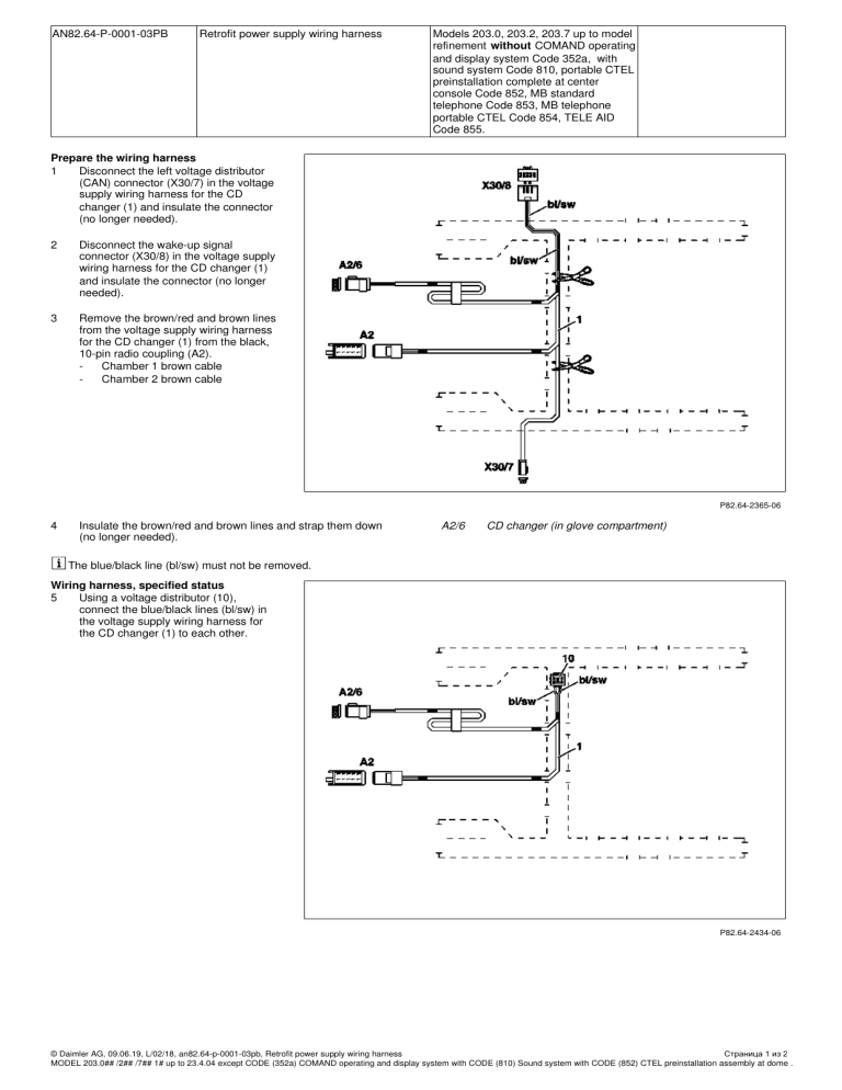
AN82.64-P-0001-03PB Retrofit power supply wiring harness Models 203.0, 203.2, 203.7 up to model refinement without COMAND operating and display system Code 352a, with sound system Code 810, portable CTEL preinstallation complete at center console Code 852, MB standard telephone Code 853, MB telephone portable CTEL Code 854, TELE AID Code 855. Prepare the wiring harness 1 Disconnect the left voltage distributor (CAN) connector (X30/7) in the voltage supply wiring harness for the CD changer (1) and insulate the connector (no longer needed). 2 Disconnect the wake-up signal connector (X30/8) in the voltage supply wiring harness for the CD changer (1) and insulate the connector (no longer needed). 3 Remove the brown/red and brown lines from the voltage supply wiring harness for the CD changer (1) from the black, 10-pin radio coupling (A2). Chamber 1 brown cable Chamber 2 brown cable P82.64-2365-06 4 Insulate the brown/red and brown lines and strap them down (no longer needed). A2/6 CD changer (in glove compartment) The blue/black line (bl/sw) must not be removed. Wiring harness, specified status 5 Using a voltage distributor (10), connect the blue/black lines (bl/sw) in the voltage supply wiring harness for the CD changer (1) to each other. P82.64-2434-06 © Daimler AG, 09.06.19, L/02/18, an82.64-p-0001-03pb, Retrofit power supply wiring harness Страница 1 из 2 MODEL 203.0## /2## /7## 1# up to 23.4.04 except CODE (352a) COMAND operating and display system with CODE (810) Sound system with CODE (852) CTEL preinstallation assembly at dome .. 6 Remove the brown/red line (br/rt), brown line (br) and blue/black lines (bl/sw) in the standard radio wiring harness from the black, 10-pin radio coupling C (A2). Contact cavity 1 brown/red line (br/rt) Contact cavity 2 brown line (br) Contact cavity 4 blue/black line (bl/sw) The black 10-pin coupling C for the radio (A2) in the standard radio wiring harness is no longer needed. P82.64-2387-01 7 Install the brown/red (br/rt) line and brown (br) line removed from the standard radio wiring harness into the black 10-pin coupling for the radio (A2) in the voltage supply wiring harness for the CD changer (1). Contact cavity 1 brown/red line (br/rt) Contact cavity 2 brown line (br) 8 Using a voltage distributor, connect the blue/black line (bl/sw) in the standard radio wiring harness to the blue/black line (bl/sw) in the voltage supply wiring harness for the CD changer (1). P82.64-2388-01 9 Use a knife to cut out the perforation in the glove compartment (see arrow). P82.64-2376-01 10 Route the 3-pin black coupling of the voltage supply wiring harness (1) as per the illustration behind the instrument panel carrier through the cutout and into the glove compartment. P82.64-2377-01 © Daimler AG, 09.06.19, L/02/18, an82.64-p-0001-03pb, Retrofit power supply wiring harness Страница 2 из 2 MODEL 203.0## /2## /7## 1# up to 23.4.04 except CODE (352a) COMAND operating and display system with CODE (810) Sound system with CODE (852) CTEL preinstallation assembly at dome ..
