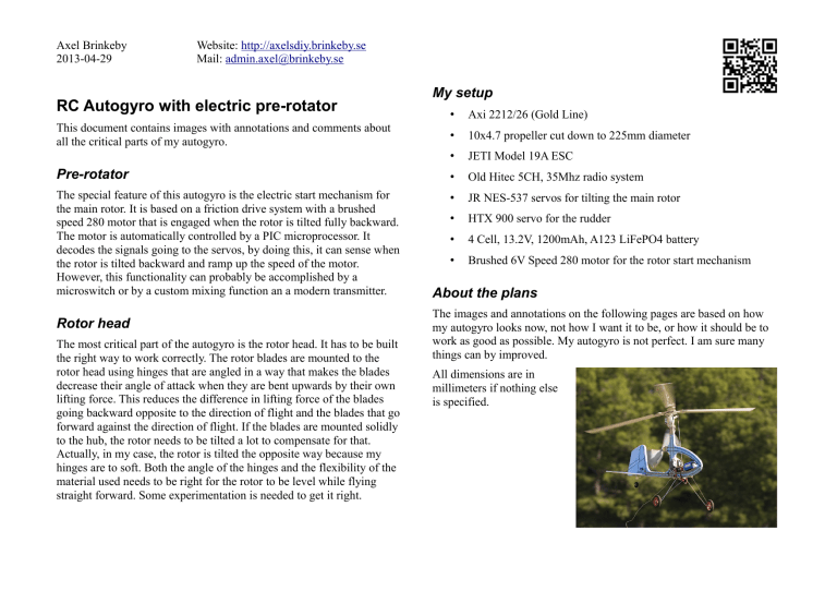
Axel Brinkeby 2013-04-29 Website: http://axelsdiy.brinkeby.se Mail: admin.axel@brinkeby.se RC Autogyro with electric pre-rotator My setup • Axi 2212/26 (Gold Line) • 10x4.7 propeller cut down to 225mm diameter • JETI Model 19A ESC Pre-rotator • Old Hitec 5CH, 35Mhz radio system The special feature of this autogyro is the electric start mechanism for the main rotor. It is based on a friction drive system with a brushed speed 280 motor that is engaged when the rotor is tilted fully backward. The motor is automatically controlled by a PIC microprocessor. It decodes the signals going to the servos, by doing this, it can sense when the rotor is tilted backward and ramp up the speed of the motor. However, this functionality can probably be accomplished by a microswitch or by a custom mixing function an a modern transmitter. • JR NES-537 servos for tilting the main rotor • HTX 900 servo for the rudder • 4 Cell, 13.2V, 1200mAh, A123 LiFePO4 battery • Brushed 6V Speed 280 motor for the rotor start mechanism This document contains images with annotations and comments about all the critical parts of my autogyro. Rotor head The most critical part of the autogyro is the rotor head. It has to be built the right way to work correctly. The rotor blades are mounted to the rotor head using hinges that are angled in a way that makes the blades decrease their angle of attack when they are bent upwards by their own lifting force. This reduces the difference in lifting force of the blades going backward opposite to the direction of flight and the blades that go forward against the direction of flight. If the blades are mounted solidly to the hub, the rotor needs to be tilted a lot to compensate for that. Actually, in my case, the rotor is tilted the opposite way because my hinges are to soft. Both the angle of the hinges and the flexibility of the material used needs to be right for the rotor to be level while flying straight forward. Some experimentation is needed to get it right. About the plans The images and annotations on the following pages are based on how my autogyro looks now, not how I want it to be, or how it should be to work as good as possible. My autogyro is not perfect. I am sure many things can by improved. All dimensions are in millimeters if nothing else is specified.
