Temperature compensation of crystal oscillators using microcontroller- spl mu CTCXO
реклама
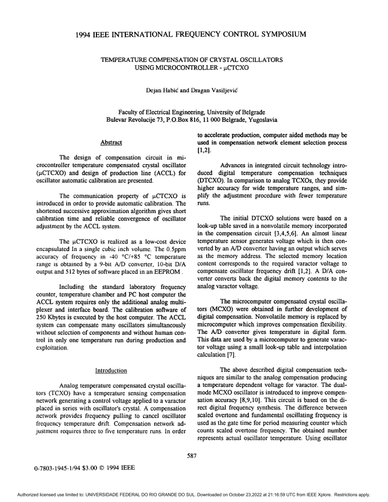
1994 IEEE INTERNATIONAL FREQUENCY CONTROL SYMPOSIUM TEMPERATURE COMPENSATION OF CRYSTAL OSCILLATORS USING MICROCONTROLLER - pCTCX0 Dejan Habid and Dragan VasiljeviC Faculty of Electrical Engineering, University of Belgrade Bulevar Revolucije73, P.O.Box 816, 11 000 Belgrade, Yugoslavia to accelerate production, computer aided methodsmay be used in compensation network element selection process Abstract [1,21. miThe design of compensation circuit in crocontroller temperature compensated crystal oscillator (pCTCXO) and designofproduction line (ACCL) for oscillator automatic calibrationare presented. The communicationproperty of pCTCX0is introduced in order to provide automatic calibration. The shortened successive approximation algorithm gives short calibrationtime and reliableconvergenceofoscillator adjustment by the ACCL system. The pCTCXOisrealized as alow-costdevice encapsulated In a single cubic inch volume. The O.5ppm accuracy of frequency in -40 "C/+85 "C temperature range IS obtained by a%bit A/D converter,10-bitD/A output and 5 12 bytes ofsoftware placedin anEEPROM . Including the standard laboratory frequency counter, temperature chamber and PC host computer the ACCL system requires only the additional analog multiplexer and interfaceboard. The calibrationsoftware of 250 Kbytes is executed by the host computer. The ACCL system can compensate many oscillators simultaneously without selection of components and without human control in only one temperature run during production and exploitation. Advances in integrated circuit technology introduced digital temperature compensation techniques (DTCXO). In comparison to analog TCXOs, they provide higher accuracy for wide temperature ranges, and simpl@theadjustmentprocedurewithfewertemperature runs. The initial DTCXO solutions were based on a look-up table saved in a nonvolatile memory incorporated in the compensationcircuit[3,4,5,6]. An almostlinear temperature sensor generates voltage whch is then converted by an M D converter having an output which serves as the memory address. The selected memory location contentcorrespondstotherequiredvaractorvoltageto compensate oscillator frequency drift [1,2]. A D/A converter converts back the digital memory contents to the analog varactor voltage. The microcomputer compensated crystal oscillators (MCXO) wereobtained in further developmentof digital compensation. Nonvolatile memory is replaced by microcomputer which improves compensation flexibility. The A/D convertergivestemperature in digitalform. This data are used by a microcomputerto generate varactor voltage using a small look-up table and interpolation calculation [7]. The above described digital compensation techniques are similar to the analog compensation producing a temperature dependent voltage for varactor. The dualAnalog temperature compensated crystal oscillamode MCXO oscillator is introduced to improve compentors(TCXO)haveatemperaturesensingcompensation sation accuracy [8,9,10]. This circuit is based on the dinetwork generating a control voltage applied to a varactor rect digital frequency synthesis. The difference between placed in series with oscillator's c y t a l . A compensation scaled overtone and fundamental oscillating frequency is networkprovidesfrequencypulling to canceloscillator used as the gate time for period measuring counter which frequencytemperature drift. Compensationnetworkadcounts scaled overtone frequency. The obtained number justment requires three to five temperature runs. In order represents actual oscillator temperature. Using oscillator Introduction 587 0-7803-1945-1/94 $ 3 . 0 0 0 1994 IEEE Authorized licensed use limited to: UNIVERSIDADE FEDERAL DO RIO GRANDE DO SUL. Downloaded on October 23,2022 at 21:16:59 UTC from IEEE Xplore. Restrictions apply. (temperature dependent voltage generation approach) is shown in Figure 1. The temperature sensor voltage is digitized by an A/D converter. The CPU accepts temperature data, finds the corresponding data from the look-up table taken during calibration, and makes the interpolation to calculate the oscillator's VC0 input voltage required to obtain nominal output frequency. The voltage is converted back toanalog form by a D/Aconverter. frequency to temperature dependence data taken during temperature calibration, the microcomputer calculates the number of pulses to be deleted from the output signal in order to obtain constant frequency [S]. The dual mode MCXO realization produces high precision compensation. The purpose of this paper is to introduce a concept of microcontroller compensated crystal oscillator suitable for fully automated production. The oscillator compensation circuit is accomplished by a microcontroller (pCTCX0). It is a small, low-power and cheap device with rich resources and property to communicate, which is necessary for oscillator calibration by an automatic computer controlled line (ACCL). The proposed concept provides unsupervised fully automated temperature compensation of clystal oscillators without component selection in only one temperaturerun. Many oscillators may be calibratedrecalibrated simultaneously in productiodexploitation.The proposedcompensationconcept supports both digital compensation approaches: dual mode MCXO and classical, temperature dependent voltage generation for V C 0 input control. The general purpose 8-bit microcontrollers have all necessary resources for the realization of the described compensation circuit. The CPU renders programmability and calculations. The look-up table is saved in anonvolatile memory. The analog values are coupled to the microcomputer by A/D and D/A converters. Microcontroller resources such as frequency dividers, timedcountersand arithmeticdlogic functions may be used to realize dual mode MCXO in combination with external mixers and filters. Finally, microcontroller ability to communicate allows calibration of many oscillators in a single temperature run by a fully automated ACCL line. Oscillator identification is obtained by a hardware key connected to the microcontroller's input digital port. The pCTCXO circuit has two operating mode: calibration mode and autonomous modes. T h s paper describes the design of pCTCXO and ACCL system. Temperature compensation circuit of the pCTCX0 iselaborated in the firstsection. The automated production line ACCL is presented in the second section. Finally, experimental results are reported in the third section. The simple software which controls autonomous operation of the pCTCX0includes routines for control of the A/D and D/A subsystems and for search and interpolation of data from the look-up table. Compensation accuracy is determined by quality of components. Design of uCTCXO Communication between the pCTCX0 and ACCL system during calibration is realized through an asynchronous serial M232 interface. Calibration software The pCTCXO temperature compensation circuit pGGG-1 HARDWARE KEY TX FiX GND t l l EMPERATWE SENSOR RAM VC0 INPUT EEPROM MICROCONTROLLER Fig.1 pCI'CX0 compensation circuit. 588 Authorized licensed use limited to: UNIVERSIDADE FEDERAL DO RIO GRANDE DO SUL. Downloaded on October 23,2022 at 21:16:59 UTC from IEEE Xplore. Restrictions apply. is a part of the automated production line ACCL and not of the pCTCXO itself. Design of automated uroductionline ACCL The ACCL system is shown in Fig.2. The host computer controls the temperaturechamber and frequency counter operation through a standard E E E 488 bus interface to provide temperature adjustment and frequency measurement. The interface board is used as an adapter between the hostcomputer'sISAbus andthe asynchronous serial m 2 3 2 interface intended for communication with pCTCXOs and the analog multiplexer. Three wire serial connection allows simple handling of a large number of pCTCXOs. The intelligent analog multiplexer provides connection of oscillators signal output to the frequency counter. pTq EEE 488 Bu Host Computer oscillator is connected tothe frequency counter using analogue multiplexer. The calibration process is open when the host computer gives information about desired temperature to the chamber using 488 bus. By the same bus host computer reads frequency counter. When oscillators frequencies are stabilized, the host decides that the oscillators transient thermal regime is finished and the temperature is held constant. Then the adjustment of selected pCTCX0 is started. Using asynchronous serial interface the host computer reads the A/D converter and attempts to pull the oscillator frequencyto the nominal value through adjustment of the D/A converter input in thefirst iteration. Now the 488 interface is activated again. The hostcomputer reads the frequency counter. When the oscillator frequency is stabilized, the host computer compares it with the target frequency. If the difference is satisfactorily small, the adjustment is finished. If not, the host computer changes the D/A converter input and the Frequency Counter SIGNAL INPUT 1 I Intelligent Analog Multiplexer 1 2 3 4 ... OUT pCTCX0 No. 1 Interface Board As232 J-wi,e 1 - Asynchronous Interfate R5232 I I 255 OUT .. . pCTCX0 No. 255 R5232 t TemDerature Chamber I I Fig.2 ACCL system. The ACCL system operates under control of the calibration software executed on the host computer. The calibration process includes three tasks: communication, calibration and programming. The communication is started whenhostcomputer downloads the program for communication to all pCTCXOdevices simultaneously. Then hostcomputer and selected pCTCXO exchange the address defined by the pCTCXOs hardware key. Signal out of the selected process is continued until target frequency is achieved. When adjustment is finished, the host computer defines the new temperature point, andthe calibration at this temperature is carried out in the same way. The number of temperature points is determinedby the uncompensated oscillators frequency to temperature characteristics (hflf/AT and the desired accuracy of compensation[1,7]. Obviously, the processingtime is proportional to the number of temperature points. 589 Authorized licensed use limited to: UNIVERSIDADE FEDERAL DO RIO GRANDE DO SUL. Downloaded on October 23,2022 at 21:16:59 UTC from IEEE Xplore. Restrictions apply. When calibration is finished, the host computer programs pCTCXO's EEPROM with contents of look-up table and program for oscillator operation in autonomous regime. defined as won as a new temperature point is selected. In this way, all pCTCXOs will settle their frequencies simultaneously and adjustment time is shortened. Two problems had tobe solved during thedevelopment of the described algorithm. The first problem is the determination of the initialvalue for theD/A input in order to obtain minimum number of approximation steps and shortest adjustment time. The right choice presumes a value as close as possible to the varactor voltage which gives nominal oscillator frequency. The initial value can be estimated on the basis of experimentally determined data on influence of every bit of the D/A converter on the oscillator frequency change Af for each pCTCX0 family. These data are placed in the host computer which uses it together with the Werence hf ' between the measured operating and nominal frequency in order to estimate the starting value of the D/A converter input. ExDeriments The second problem is how to select D/A input in the second and other further steps in order to obtain convergence of the adjustment procedure. The successive AfJf The compensation circuit of pCTCX0 device is realized by a Motorola 68HCll microcontroller and by a KTY silicon temperature sensor, Fig.1. The passive second order RC filter is added to complete pulse-widthD/A converter circuit. The pCTCX0 autonomousmodeoperation is controlled by a 512 bytes program including 95 bytes look-uptable. The frequency stability better than +/-0.5ppm in the range of operating temperatures of (-40 "C , +85 "C) is obtained bya 9 bit A/D converter and 10 bit pulsewidth D/A converter, Fig. 3. The look -uptable is obtained in 30 points for AT cut crystals with uncompensated frequencytotemperaturecurve with maximumfrequency deviation At7e+/-25ppm and maximum slope (Aflf)lAT=l.Sppm/ "C. [PPml 0.7 0.5 0.3 0.l -0.1 -0.3 -0.5 -0.7 -50 Fig.3 Frequency to temperature characteristic of a compensated pCTCX0. The compensation circuit of thepCTCX0 is built by general purpose and low-cost components. The entire pCTCXO is encapsulated in a standard 36mmX27mmX19mm size case. The compensation circuit current consumption is low(lOmAI5V) in awide range of operating temperatures (-40"C, +85"C). approximation algorithm, common in ND conversion, is agood choice due to the reliable and fast convergence. The proposed procedure represents a shortened successive approximation algorithm. Whenmany pCTCXO devices are adjusted simultaneously, the input to each oscillator's D/A should be 590 Authorized licensed use limited to: UNIVERSIDADE FEDERAL DO RIO GRANDE DO SUL. Downloaded on October 23,2022 at 21:16:59 UTC from IEEE Xplore. Restrictions apply. The ACCL line includes standard instruments such as laboratoryfrequency counter and temperature chamber with IEEE 488 bus. A PCis used as a host computer (Fig.2.). The ACCL line also includes a specially designed interface board and an intelligent analog multiplexer. A 68HCll microcontroller and a RAM buffer memory make up the interface board. The analog multiplexer has the same microcontroller and an analog multiplexer tree with 255 inputs. The ACCL system is under control of a 250 Kbytes s o h a r e under DOS. The operation of fully automated ACCL system during calibration is illustrated in Fig.4. The number of attempts to obtain nominal frequency at a selected constant temperature depends onthe closeness of the varactor voltage initial value and its final value. The diagram also illustrates the convergence of the shortenedsuccessive approximation algorithm. The ACCLsystem calibration time for three pCTCXO devices is shown in FigS. The dark rectangle represents the time interval needed for temperature stabi- -5 -45 '- 1 -18 lAttempt 1 I A I 9 I approxination algorithm and time spent for oscillator settling after change of varactor voltage. The main problem in design of ACCL system is to discover efficient calibration algorithm to save adjustment time. Conclusions This paper presents the design of a temperature compensationnetwork in microcontroller compensated crystal oscillators (pCTCX0) and the design of production line (ACCL) for automatic oscillator calibration. The pCTCXO circuit is built by general purpose low cost components. It is a small, intelligent unit able to communicate with the outside world. The proposed concept of ACCL system provides fully automated, unsupervised temperature compensation of crystal oscillators withoutcomponentselection in a single temperature run. Many oscillators may be calibratedsimultaneously in productionand later, during I I 1 36 Temperature ["C] 63 90 Attempt 2 Anempl3 Attempt 4 Attempt 5 Attempt 6 Attempt 7 Attempt 8 ] Fig.4 Operation of ACCL systemduring calibration. lization in the temperature chamber and oscillators. The gray rectangles designate time consumed by the ACCL software during execution of the shortenedsuccessive exploitation. Both digital compensationapproaches are supported: dual mode MCXO and classical, temperature dependent voltage generation for VC0 input control. Ef- 59 I Authorized licensed use limited to: UNIVERSIDADE FEDERAL DO RIO GRANDE DO SUL. Downloaded on October 23,2022 at 21:16:59 UTC from IEEE Xplore. Restrictions apply. Adjustment Time [min] 30 c 20 10 0 Temperature ["C] Fig.5 Time consumption of ACCL algorithm. ficient shortenedsuccessiveapproximationalgorithm provides fast and reliable convergence. Upgrading of a standard nonautomatic calibration system to an ACCL system is inexpensive, since few lowcost additional components are needed. "A Temperature Compensated SC [4] E.K.Mgue1, Cut Quartz Crystal Oscillator," in ProceedinPS of the 36th Annual Freauencv Control SvmDosium , 1982, pp. 576-585. [5] Takehiko Uno and Yoshio Shimoda, "A New Digital TCXO Circuit Using a Capacitor-Switch Array," in Proceedinns ofthe 37th Annual Freauency Control Svmmsium, 1983, pp. 434-441. [6] Z.Aleksid and D.Vasiljevid, "Digital Temperature Compensation of Crystal Oscillators Using Temperature Switches," in Proceedings of the 40th AnnualFreauencvControl SvmDosium , 1986, pp. 340-343. [7] TMyayama, Y.Ikeda and S.Okano t'ANew Digtally Temperature Compensated Crystal Oscillator for a Mobile Telephone System,"in Proceedinm of the 42nd Annual Freauencv Control SvmPosium , 1988, pp. 327-333. [S] A.Benjaminson and S.C.Stallings, "A Microcomputer-Compensated Crystal Oscillator Using A Dual Mode Resonator,I' in Proceedinm of the 43rd Annual Freauencv Control Svmwsium , 1989, pp. 20-26. Currently, we are investigating further calibration algorithm improvements to shorten the calibration time even more. References M.E.Frerking, "Method of Temperature Compensation," in Proceedings of the 36thAnnual Frequency Control Svmposium , 1982, pp. 564-570. V.Candelier, G.Caret and A.Debaisieux, "Low ProfileHighStabilityDigitalTCXO;Ultra Low Power Consumption TCXO,"in Proceedings of the 43rdAnnualFreauencvControl SvmDosium , 1989, pp. 51-53. RRubach, "Dual Mode Digitally Temperature Compensated Crystal Oscillator," in Proceedings of the36th Annual Freuuencv Control Svmpo1982, pp, 571-575. m, 592 Authorized licensed use limited to: UNIVERSIDADE FEDERAL DO RIO GRANDE DO SUL. Downloaded on October 23,2022 at 21:16:59 UTC from IEEE Xplore. Restrictions apply. [g] RL.Filler, J.A.Messina and V.J.Rosati, "Frequency-Temperameand Ageing Performance of Microcomputer-CompensatedCrystal Oscillators," in Proceedings of the43rdAnnualFreauencv Control Svmwsium , 1989, pp. 27-33. [lo] M.Bloch, M.Meirs, J.Ho, J.R.Vig and S.Schodowski,"LowPowerTimekeeping ," in Proceedings of the 43rd Annual Freuuencv Control Svmmsium , 1989, pp. 34-36. 593 Authorized licensed use limited to: UNIVERSIDADE FEDERAL DO RIO GRANDE DO SUL. Downloaded on October 23,2022 at 21:16:59 UTC from IEEE Xplore. Restrictions apply.
