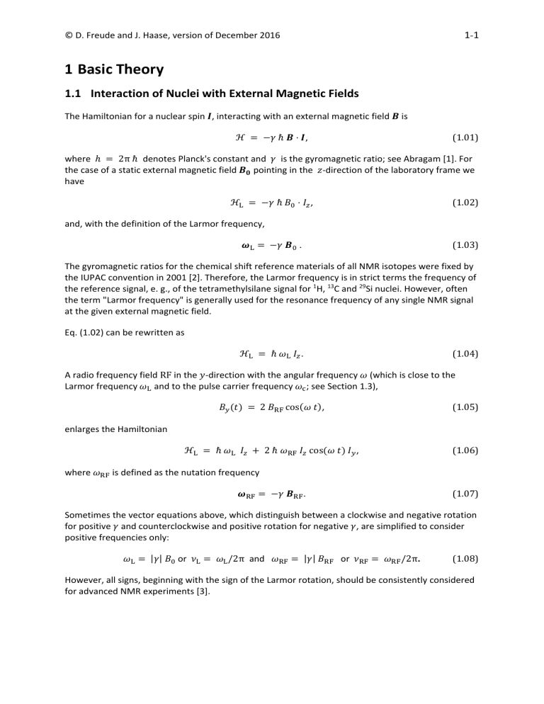
1-1 © D. Freude and J. Haase, version of December 2016 1 Basic Theory 1.1 Interaction of Nuclei with External Magnetic Fields The Hamiltonian for a nuclear spin , interacting with an external magnetic field is ⋅ , (1.01) where 2π denotes Planck's constant and is the gyromagnetic ratio; see Abragam [1]. For the case of a static external magnetic field pointing in the ‐direction of the laboratory frame we have ⋅ , (1.02) . (1.03) and, with the definition of the Larmor frequency, The gyromagnetic ratios for the chemical shift reference materials of all NMR isotopes were fixed by the IUPAC convention in 2001 [2]. Therefore, the Larmor frequency is in strict terms the frequency of the reference signal, e. g., of the tetramethylsilane signal for 1H, 13C and 29Si nuclei. However, often the term "Larmor frequency" is generally used for the resonance frequency of any single NMR signal at the given external magnetic field. Eq. (1.02) can be rewritten as (1.04) . A radio frequency field RF in the ‐direction with the angular frequency (which is close to the Larmor frequency and to the pulse carrier frequency ; see Section 1.3), 2 cos (1.05) , enlarges the Hamiltonian 2 where cos (1.06) , is defined as the nutation frequency (1.07) . Sometimes the vector equations above, which distinguish between a clockwise and negative rotation for positive and counterclockwise and positive rotation for negative , are simplified to consider positive frequencies only: | | or /2π and | | or /2π. (1.08) However, all signs, beginning with the sign of the Larmor rotation, should be consistently considered for advanced NMR experiments [3]. 1-2 © D. Freude and J. Haase, version of December 2016 1.2 Irreducible Tensor Operator Calculus It is useful to express the internal interactions of a nuclear spin in the notation of irreducible tensor denotes one of the (2k + 1) components of an irreducible tensor operators; see Weissbluth [4]. If operator of rank , then it is transformed under a coordinate rotation, ′ , to , , , 1, … , , 1.09 denotes the matrix elements of the irreducible representation of the group of where ordinary three‐dimensional rotations (Wigner D‐Matrix [5]). We use here the index in agreement with the majority of the literature. It is not generally identical to the magnetic quantum number . The transformation operator is given by exp i ∙ , 1.10 where is the total angular momentum operator, is the unit vector pointing in the direction of rotation, and represents the angle of rotation. Such a rotation transforms the eigenfunctions, | of the angular momentum operator of a nuclear spin , as | where | , , 1.11 denotes the Wigner D‐matrix. The Wigner D‐matrix can be rewritten by means of Wigner's : small d‐matrix (also called the "reduced real" Wigner Matrix) , , exp i ′ exp i . (1.12) Table 1.1 gives values of the D‐Matrix for ranks 1/2 and 2. The d‐matrix elements from rank ½ up to rank 5 can be found in the textbook of Varshalovitch et al. [6], where M and M' are used instead of m' and m, respectively. Eq. (1.12) is the most common relation between the D‐ and d‐ matrices [7]. A slightly different form using plus instead of minus signs in Eq. (1.12) holds for Euler angles on the base of the left‐hand screw rule [4, 5] and was given in our previous review [8]. The different conventions of the Euler angles were compared by Goldstein et al. [7] and Morris and Parker [9]. A detailed description of active and passive rotations with Euler angles in NMR was recently presented by Millot and Man [10]. Currently, the most common conventions [7] employ the right‐hand screw rule for the angle directions and are termed ′ ′′ and ′ ′′. We use the latter of these two conventions [11]. As presented in Fig. 1.1, a transformation of the frame , , to the frame ′′, ′′, ′′ by Euler angles includes the rotation about the original axis, the rotation about the obtained ′ axis, and the rotation about the final ′′ axis. Fig. 1.1. Definition of the Euler angles corresponding to the right‐hand screw rule for angles rotating around the z‐, y'‐, and z''‐axes. . 1-3 © D. Freude and J. Haase, version of December 2016 Table 1.1. Wigner D‐Matrix elements for rank k = ½ and k = 2. ½ k=½ ′ ′ ½ cos sin e ½ 2 k=2 ′ 2 ′ 1 ′ 0 ′ 1 ′ 2 e e e e sin cos e e e sin e e cos e 1 e sin e ½ e e 0 sin 1 e e sin cos e cos 1 e e e sin cos e sin cos e sin 2 e sin e e e e e 1-4 © D. Freude and J. Haase, version of December 2016 A definition of an irreducible tensor operator that is equivalent to Eq. (1.09) is given by the commutators [4]. If instead of the total angular momentum operator only the nuclear spin concerned, we have , , , ∓ 1 is 1 /2 (1.13) i . (1.14) with ∓ , /√2, and , of two operators with the components The tensor product, ′ ′| and is defined as [4] ′ 1.15 , The term ′ ′| ′ introduces the Clebsch‐Gordan coefficients [6]. is an irreducible is the scalar component of that tensor operator and, given the properties of the tensor operator. Clebsch‐Gordan coefficients, it is found that 1 √2 1 1 , , 1, … , . 1.16 and Most interactions in NMR can be written in this form [12]. It is important that the operators mostly act on two different non‐interacting systems, the nuclear spin coordinates and spatial coordinates (framework parameters), respectively. Irreducible tensor calculus is most useful when coordinate transformations have to be considered, as in the case of the transformation to the principle axis system (PAS) of a tensor, e.g., for the description of sample spinning. 1.3 Rotating Frame NMR spectrometers use RF pulses with a carrier frequency near the Larmor frequency , perform a phase sensitive detection and a Fourier transform, and provide a signal at the resonance offset Δ . Therefore, it is most useful to perform a transition into a frame rotating with an angular frequency by separating out the Hamiltonian . The total Hamiltonian in the Schrödinger representation can be written as . To switch from the Schrödinger representation (s) to the interaction representation (i), the wave function | and any operator must be transformed by the unitary operator exp (1.17) , so that [13] | | , (1.18) . in the interaction The equations of motion for the wave function and the density operator representation are [13] | , | , , , . (1.19) 1-5 © D. Freude and J. Haase, version of December 2016 Using , and the resonance offset Δ interaction representation, according to Eq. (1.17), Δ , , we have for the Hamiltonian in the exp i exp i (1.20) . A formal solution to the equation of motion of the density operator, Eq. (1.19), is obtained by the unitary evolution operator , : , , The evolution operator , obeys the equation , If the operator , (1.21) . , , (1.22) . is time‐independent, the solution is , exp (1.23) . , The general solution to Eq. (1.22) employs the Dyson time‐ordering operator, , exp , , d [14]: (1.24) . The Magnus expansion [15] can be used in order to describe the evolution of a time‐dependent, but with integer N: periodic Hamiltonian, , , , 0 exp ⋯ , , , (1.25) where 1 i d , , and the odd terms disappear for d 2 , , d , , 1.26 . For higher‐order terms see [12]. The Hamiltonian for the static field in the ‐direction is in the rotating frame instead of the laboratory axis system (LAB), see Eq. (1.04), , Δ , where Δ (1.27) . The ‐pulse of the magnetic RF field corresponds to 1 , cos2 sin2 , (1.28) which, neglecting the time‐dependent part, reduces to (1.29) . , If ϕ is the phase difference of the pulse with respect to the y‐direction, positive for a right‐handed screw in the positive direction along the axis of rotation, one has from Eq. (1.10) , exp i exp i . (1.30) 1-6 © D. Freude and J. Haase, version of December 2016 1.4 Free Induction Decay (FID) and Line Shape By means of phase‐sensitive quadrature detection, the demodulated free induction decay (FID) is digitized into two sets of data where a unique time difference between the two sets corresponds to a 90° phase shift of the carrier frequency of the RF pulse. Thus, the FID is a complex voltage and can be calculated as the relaxation function ~ tr | ≡ tr , 1 1.31 with 1 being the unity operator [1, 14]. The high‐temperature approximation, ‖ ‖ ≪ , and the Magnus expansion were introduced [12] to achieve a density operator proportional to Iz for a single spin I. The obtained convention is | | (1.32) . Then the FID is given by tr | ≡ tr | , , | . | 1.33 represents the density operator after the pulse, See also Eq. (1.21), where 0. As a good approximation, one can consider only operators in , which are secular with respect to the Zeeman interaction. With 1 1 (1.34) 1 (looking ahead to Eq. (2.23)), we find for Eq. (1.33): 1 2 tr , , , . 1.35 It should be mentioned that in the present review the transition → 1 is considered. One also finds the transition 1 → in the literature, with the central transition being . The two notations are essentially the same despite the difference in the signs of their imaginary parts. The transverse relaxation time, T2, is an important parameter for the characterization of the free induction decay. It is commonly defined as the time difference, / , between the maximum initial ⁄e, where e is the base of the natural logarithm. 0 and the value / value / The Fourier transform of the relaxation function exp Since exp is diagonal in the set | 1 tr 2 , gives the line shape function i d . : 1.36 , we obtain for the observed signal , , / . 1.37 1-7 © D. Freude and J. Haase, version of December 2016 , , We have and . The different interactions, , , generate the frequency distribution. The elements of the density operator, , , contain the information about the excitation; see Section 2. An important parameter of the broadening of the line shape, , in solid‐state NMR spectra of powder materials is the second moment. We express the second moment as an integral over the spectral range d . (1.38) The normalization of the line shape function, d 1, (1.40) and the definition of the first moment, d 0, (1.39) were used in Eq. (1.38). The center of gravity is shifted with respect to the Larmor frequency by contributions from isotropic shifts like isotropic chemical shifts or isotropic second‐order quadrupole shifts. The dimension of the second moment is s2. It changes to Hz2 or T2 if the line shape is given as or , respectively. ⁄s ⁄Hz ⁄T 1⁄2 π The corresponding dimensionless equation is for a correspondingly changed normalization in Eq. (1.40). It should be noted that for a Lorentzian line shape 1 , 1.41 π the second moment increases to an infinite value with increasing bounds of integration. The half width at half intensity, δ , is defined as angular frequency by [1] (1.42) . But the full width at half maximum (fwhm) is commonly used now as a measure for the line width. The ≡ δ / is defined by δ The relation to the line width parameter (1.43) . / πδ in Eq. (1.41) is / . A Lorentzian line shape exp corresponds to a single‐exponential decay of the relaxation function transverse relaxation time with the . The frequency and time domain are connected by 1 or δ 1 / π . 1.44 For the Gaussian line shape 1 2π exp 2 , knowledge of the second moment provides the exact line width, in theory. It is provided in s 2, for the fwhm given in Hz and 1.45 ln 4 [1] or, 1-8 © D. Freude and J. Haase, version of December 2016 δ ln 4 π / Hz s 0.375 . s 1.46 It is possible to obtain a rough estimation of the line broadening of a signal by assuming a Gaussian line shape and using Eq. (1.46). Equations for the calculation of second moments for different interactions will be given in the next sections. 1.4 Electric Quadrupole Interaction 0 We have two values describing the traceless electric field gradient tensor in the principle axis system, PAS, with upper‐case coordinates , , : , . 1.47 The asymmetry, , of the electric field gradient is in the range 0 1, if we label the axis so that | | | |. Additional explanations will be given after Eq. (1.94). The value is | | exclusively used in a product with the elementary charge . The Hamiltonian of the electric quadrupole interaction, as presented by Abragam [1] page 232, is 4 2 1 1 3 1 2 4 2 . 1.48 1 3 1 is the quadrupole moment, and is called the electric quadrupole moment. The quadrupole coupling constant, , is commonly defined with Planck's constant as . The quadrupole frequency, 3 2 2 1 or 3 2 2 1.49 , is defined by Abragam, see [1] (page 233), as 1 or 3 2 2 1 3π 2 1 . 1.50 It can be seen in Fig. 1.2 that for 0 the quadrupole frequencies and correspond to the frequency distance between the singularities in the powder pattern for the 3/2 ↔ 1/2 transitions. This is equal to the maximum first‐order quadrupole frequency shift with respect to the Larmor frequency for one satellite transition. Eq. (1.50) is now the commonly used definition of the quadrupole frequency for half‐integer spin nuclei in the field of NQR. But for 1 nuclei no notational consistency exists, and other definitions of can be found [16]. Some differing definitions exist in the literature also for half‐integer spin nuclei. For a comparison, we apply Abragam's definitions of , Eq. (1.50), and the corresponding and from Eq. (1.58). Then we use ∗ or ∗ in place of the angular dependent definitions of 6 ∗ by Amoureux and various definitions used by the below‐mentioned authors. The result is 2 ∗ by Deschamps and Massiot [18], p.187; 2 ∗ by Man [19], p. 8, Pruski [17], p. 145, 3 ∗ by Frydman and coworker [20], and by Ashbrook and Wimperis [3], p. 48; and in the past, ∗ 6 by Samoson et al. [21], Nielsen et al. [22] and Veeman [23]. p. 5375; and 1-9 © D. Freude and J. Haase, version of December 2016 The quadrupole interaction can be regarded as a scalar product of two irreducible tensor operators of rank two [12], the tensor of the electric field gradient and the quadrupole tensor; see Eq. (1.16). Using this notation the quadrupole interaction is described by 2 2 1 1 , 1.51 where √ 1 , 3 , √ ∓ , (1.52) , √ (1.53) and, in the principle axis system (PAS) of the electric field gradient tensor, , 0, (1.54) . The transformation from the PAS , , to the laboratory axis system (LAB) or to any arbitrary frame , , can be performed by three successive rotations: about the ‐axis, about the component we revise Eq. (1.09) in light of obtained ′‐axis, and about the ‐axis. For the new Eq. (1.12) and Table 1.1 to sin which is needed for the part of denoted by cos2 that commutes with the Zeeman Hamiltonian 1 3 By substituting sin sin cos2 cos2 , (1.55) . This part is . (1.56) and using Eq. (1.47) we obtain sin cos2 3 1 . (1.57) Given the angular dependent quadrupole frequency 3cos 1 2 2 sin cos2 , 1.58 one can write 6 3 1 . 1.59 In the interaction representation we have instead of Eq. (1.51), , 2 2 1 1 exp i . Using the Magnus expansion [12], we obtain similarly to Eq. (1.59) the first‐order contribution, 1.60 1-10 © D. Freude and J. Haase, version of December 2016 3 6 1 . 1.61 From the second‐order contribution, the secular part with respect to Iz is 9 2 1 2 1 4 1 1 2 . 1.62 The irreducible tensor components in the laboratory axis system (LAB) or in any arbitrary frame , , can be expressed by the principle axis components using , , . 1.63 Quadrupole powder patterns of half‐integer nuclei with first‐order and second‐order quadrupole interaction have already been calculated for a symmetric field gradient by Bloembergen, as presented in the review of Cohen and Reif [24]. Spectra describing the combined effect of quadrupole interactions and chemical shifts were first presented by Jones et al. [25]. A review of powder spectra in NMR and EPR was given by Taylor et al. [26] in 1975. For stronger quadrupole interactions, which cannot be described by perturbation theory, the eigenvalue problem of the full Hamiltonian has to be solved. Barnes et al. [27] briefly reviewed the work in this field performed up until 1988, when the standard assumption or condition was that the quadrupole and chemical shift tensors be coincident. Examples of low‐symmetry sites that do not meet this condition were studied by Cheng et al. [28], Power et al. [29] and Skibsted et al. [30] describing the line shapes of 85,87Rb in rubidium salts, 133Cs in cesium chromate and 51V MAS spectra, respectively. An effective procedure for the powder average was introduced by Alderman et al. [31]. This approach provides a very fast simulation of powder patterns since, first, the intensity for a special orientation is averaged over the next‐nearest orientations, and second, the time‐consuming calculation of trigonometric functions could be replaced by simple division. Extensions by Sethi et al. [32] and Zheng et al. [33] allow the computation of centerband and sideband intensities of the central transition for any angle and speed. The first‐order quadrupole powder pattern can be obtained with from Eq. (1.61) by assuming the resonance offset to be zero. Then, the first‐order frequency shift becomes, with Eq. (1.58), 3cos , The central transition corresponds to 1 2 2 sin cos2 1 2 1 . 2 1.64 and is not shifted by the first‐order interaction. In order to calculate the line shape one has to make assumptions about the excitation; see Section 2. Here we limit the considerations to nonselective excitation and have for a ‐pulse in the y‐direction . Fig. 1.2 gives some examples of the line shapes of random powders. The theoretical line shape is slightly Gaussian‐broadened, in order to avoid singularities. The line at the Larmor frequency due to the central transition is cut off. It can be seen in Fig. 1.2 that the spectral width of a first‐order quadrupole‐broadened spectrum amounts to 2 1 . Magic‐angle spinning (MAS) eliminates the first‐order quadrupole broadening, if the MAS frequency is larger than the spectral width. In the case in which the spinning frequency is much smaller than the spectral width, we obtain spinning sideband spectra with envelopes corresponding to the static spectra in Fig. 1.2. 1-11 © D. Freude and J. Haase, version of December 2016 Figure 1.2. Examples of the static line shape (without MAS) of first‐ order quadrupole‐broadened powder spectra for non‐selective excitation. The signal of the central transition is not fully displayed (cut off). from Eq. (1.62). The second‐order quadrupole powder pattern can be obtained with The calculation based on Eq. (1.35) of quantum transitions , , , 24 6 18 / (see) yields with zero‐offset for single‐ 1 1 4 2 1 1 9 3 . 1.65 For symmetric (single and multiple) quantum transitions, we obtain , 4 2 9 1 1 1 1 8 2 . 1.66 The components are given in LAB notation. Using Wigner matrices of rank 2, they can be described as functions of the corresponding values in the PAS notations, which are given in Eq. (1.54). The in Eqs. (1.65) and (1.66) can also be written as Wigner matrices of ranks as high as 4. products It is possible to express the products in LAB (also via the system of the spinning rotor and the time‐average of about one rotation period) in terms of PAS with a function of the Euler angles , and the asymmetry parameter : , , , cos , cos , . (1.67) Samoson [34] split the second‐order quadrupole shift into an isotropic part (iso) describing the quadrupole shift of the center of gravity of the signal and an angular‐dependent anisotropic part describing the quadrupole broadening of the signal: 1-12 © D. Freude and J. Haase, version of December 2016 , , , 1 5 6 1 9 17 3 1 1 3 1 13 6 1 3 . 1.68 , , This separation is very useful, since the isotropic shift corresponds to the center of gravity of the second‐order quadrupole‐broadened signal. The powder average about the function , , is zero, as can be shown using the functions in Table 1.2 and performing the corresponding integrations. The terms A, B, and C for Eq. (1.67) are given in Table 1.2 for the static case (no sample rotation) and for the case of fast magic‐angle spinning. Similar terms for the static case were first presented by Narita et al. [35] with special Euler angles and rewritten by Baugher et al. [36] for the Euler angles that are used here. Similar terms for MAS were first given by Müller [37]. Both sources provide the sum of isotropic and anisotropic contributions, whereas Table 1.2 presents the anisotropic contribution with the powder average of zero. The original equation g by Samoson [34] contains printing mistakes in three terms. Table 1.2. Functions A, B, and C in the equation , , , cos , cos , , Eq. (1.67), for the anisotropic part of the second‐order line shapes of single‐quantum transitions for static and MAS conditions. Function Static case A cos 2 B 2 cos 2 MAS cos 2 cos 2 cos 2 C cos 2 cos 2 cos 2 cos 2 cos 2 cos 2 cos 2 We obtain identic results from Eqs. (1.65) and (1.66) if we insert the quantum number m = 1/2 for the central transition. The square brackets in Eqs. (1.65), (1.66) and (1.68) are then multiples of 1 and the result is / , / 3 4 1 6 1 1 5 3 , , 1.69 with , , as gstatic or gMAS from Table 1.2. The first summand and , , in the curly brackets of Eq. (1.69) describe the isotropic and anisotropic contribution, respectively. In Fig. 1.3 we show some examples of second‐order quadrupole‐broadened powder spectra (random powder) of the central transition, without sample spinning (static) and with MAS. Fig. 1.3 uses the scaling factor 16 1 3 , 4 1.70 which was introduced by Cohen and Reif [24] as a convenient measure for the width of the second‐ order broadened spectrum. It should not be confused with function A in Eq. (1.67). On this scale, the spectral width for the MAS spectra is 72 A/63 and 98 A/63 for = 0 and 1, respectively, in comparison to 25 A/9 and 40 A/9 for the static spectra at = 0 and 1, respectively. 1-13 © D. Freude and J. Haase, version of December 2016 Fig. 1.3. Examples of the line shapes, static and with MAS, of second‐order quadrupole‐broadened powder spectra of the central transition. The theoretical line shapes are slightly Gaussian broadened. In order to deduce the quadrupole parameters from experimentally obtained MAS spectra, it is usual to fit the experimental spectrum with calculated spectra using a utility program adapted to the spectrometer software. The freely accessible program dmfit by Massiot et al. [38] is widely used for the simulation of quadrupole broadening of NMR signals. For a rough estimation we introduce, using (Eq. 1.69), the angular frequency of the isotropic second‐order quadrupole shift of the central transition, Δ 3 4 1 30 1 3 , 1.71 and we obtain [39] for the second moment of the line shape with respect to the center of gravity for the static sample, Δ (1.72) . In the case of MAS with a spinning speed larger than the second‐order broadening of the central transition, neglecting spinning sidebands, the result is Δ . (1.73) 3.6 (1.74) From Eqs. (1.72) and (1.73) it is found that the factor describes the reduction of the second‐order line broadening by means of MAS [39]. 1-14 © D. Freude and J. Haase, version of December 2016 Eq. (1.72) allows the estimation of the isotropic quadrupole shift, Δ or Δ , from the fwhm, δ / , of the MAS signal under the conditions that the signal is exclusively broadened by second‐ order quadrupole interaction and that the line shape can be approximated by a Gaussian line. Then the application of Eq. (1.91), see below, gives in connection with Eq. (1.74) δ Δ (1.75) . / This means that the isotropic shift amounts to 0.85‐fold of the fwhm of the MAS signal. The minus‐ sign in Eq. (1.71) means that the isotropic quadrupole shift decreases the resonance frequency and accordingly shifts the signal position to the right side on the ppm‐scale. The use of different symmetric transitions is the basis of multiple‐quantum MAS NMR spectroscopy. We introduce the quantum level p. Symmetric coherences then have the notation /2 ↔ /2 instead of ↔ . The central transition corresponds to 1. Amoureux et al. [40, 41] calculated the shifts of the symmetric transition in the case of very fast sample rotation around the magic‐angle arccos 3 / 54.74°. In that case, the contributions from the rank 2 components disappear and the rank 4 components give in our notation / , , , , / 6 1 1 5 17 36 1 5 18 3 4 1 18 7 3 cos . , , The anisotropic contribution (bottom in Eq. 1.76) is again described by the function see Table 1.2. But the rank 4 contribution still contains the fourth Legendre polynomial cos 35 cos 30 cos 3 1.76 , , ; (1.77) as a function of the rotation angle. We can insert here the magic angle with cos 1/√3 and obtain cos 7/18. Then, the value of the smaller curly bracket in Eq. (1.76) becomes 1, and disappears as a factor. This form is the fundamental equation for the MQMAS NMR spectroscopy of quadrupolar nuclei with half‐integer spins. However, we can insert instead of the magic angle one of the second angles for double rotation (DOR), arccos 6 96/5 /14 30.56° or 70.12°. Then the Legendre polynominal P4 in Eq. (1.76) is equal to zero and the total anisotropic part disappears. This is the fundamental scheme for DOR NMR. 1-15 © D. Freude and J. Haase, version of December 2016 1.5 Magnetic Dipolar Interaction between Nuclei We have number of nuclei in the sample and consider the dipolar interaction of a selected nucleus , where 1, 2, … , , with any other nucleus defined as , where 1, 2, … , . The Hamiltonian, describing the interaction between the magnetic moments of the two nuclei with is the distance 3 ∙ ∙ ∙ 4π . 1.78 Using the irreducible tensor notation one may write [12, 14] 1 , 1.79 where we have generally and for a coordinate system with ‐axis parallel to √ 3 , ∙ , ∓ √ , , , √ , , , , 3 cos , 0. , the part of [1] is 1 3 For heteronuclear dipolar interaction (unlike spins S), 4π 2 , 0, For homonuclear dipolar interaction (like spins I), of spins with the distance , , for a pair , 4π 2 , , ∙ , , , (1.80) commuting with . 1.81 , we have 3 cos 1 2 , , . 1.82 I, S denote the spins of the resonant and non‐resonant nuclei, respectively. The second moment (powder average) of the corresponding line shape is given in Ref. [1] for like spins in the case that the dipolar interaction of a spin pair with the distance rik is large compared with the quadrupole interaction: 9 5 4π 1 1 3 . 1.83 For unlike spins, the second moment is [1] 4 5 4π 1 1 3 . 1.84 1-16 © D. Freude and J. Haase, version of December 2016 The total second moment of the type‐I spins is . The latter heteronuclear contribution to the second moment remains the same, if a strong quadrupole interaction is present [1]. In contrast, the quadrupole interaction can reduce the second moment of the contribution of the 2 1 (first‐order spectral width) becomes larger homonuclear dipole interaction, Eq. (1.83), if than the homonuclear dipolar broadening [1, 8]. Spin‐flipping between different transitions is then prohibited, and the second moment decreases. The reduction is less than 20%, if the second‐order broadening of the central transition, indicated by parameter A in Eq. (1.70), is still smaller than the homonuclear broadening. The reduction factor of the homonuclear contribution to the second moment becomes 4/9, if A is much larger than the homonuclear dipolar broadening. This then means that the I‐spins are hypothetical unlike spins that can be described by one gyromagnetic ratio ; compare Eqs. (1.83) and (1.84). The pure dipolar second moment of a spin system consisting of N resonant spins of type I (homonuclear interaction of spins with the distance rI) and M non‐resonant spins of type S (heteronuclear interaction of spins with the distance rS) can be determined by the dimensionless equation /Hz /s /T 1.85 /m /m 2π with 3 1 , 1.86 5 4π 4 15 1 1 1 1 , , 4π 1 1.87 1 1 . 1.88 , 1.89 Eqs. (1.85) (1.89) can be used for the calculation of the dipolar second moment. Table 1.3 provides the coefficients for a special dimensionless equation using the non‐SI units Gauss and Ångström, where the second moment is given in G units (and divided by G ) and the is given in Å (and divided by Å) [42]: distances /G ⁄Å /T ⁄Å 10 1.90 The value of a non‐resonant nucleus can be easily calculated from the value of the same resonant nucleus by 4/9. The distances rI and rS denote in a simple model the internuclear distances of one resonant spin to another resonant spin and to a non‐resonant spin, respectively. For the general case, rI and rS have to be calculated by means of Eqs (1.88) and (1.89), respectively. Another dimensionless equation is very helpful, in order to correlate the second moment of a line, which is broadened by any interaction, to the line width, which is described by ≡ δ / . Under the assumption of a Gaussian line shape, with as the transverse relaxation time in seconds and the line width δ / given in Hz, we obtain /s where 2 /s has the unit s δ / : /Hz /s π ln 4 7.12 /T δ / Hz or 10 δ / Hz 0.3748 /G . /s , 1.91 1-17 © D. Freude and J. Haase, version of December 2016 Table 1.3. Values of CI in Eq. (1.90) for some nuclei. Values of CS can be obtained by CS = 4/9 CI. The gyromagnetic ratios were taken from Ref. [43]. nucleus 1 H 2 H 7 Li 9 Be 10 B 11 B 13 C 14 N 15 N 17 O 19 F 23 Na 27 Al 29 Si 31 P 35 Cl 37 Cl 51 V 55 Mn 59 Co CI spin γ /107 s−1T−1 nucleus 358.167 22.5064 270.527 35.3699 66.1705 184.411 22.6555 4.99055 3.68250 76.8540 317.343 125.460 284.158 14.1588 58.7999 17.2317 11.9395 521.687 257.831 421.373 1/2 1 3/2 3/2 3 3/2 1/2 1 1/2 5/2 1/2 3/2 5/2 1/2 1/2 3/2 3/2 7/2 5/2 7/2 26.7522128 4.10662919 10.3977013 3.759666 2.8746786 8.5487044 6.728284 1.9337792 10.136767 3.62808 25.18148 7.0808493 6.9762715 5.3190 10.8394 2.624198 2.184368 7.0455117 6.6452546 6.332 63 Cu Cu 75 As 77 Se 79 Br 81 Br 87 Rb 93 Nb 117 Sn 119 Sn 121 Sb 127 I 133 Cs 195 Pt 199 Hg 201 Hg 203 Tl 205 Tl 207 Pb 209 Bi 65 CI spin γ /107 s−1T−1 126.559 144.697 52.8599 13.1468 113.188 131.518 193.178 712.306 46.0144 50.3634 242.413 169.598 131.200 17.0596 11.7516 8.00653 120.846 123.235 15.5850 316.108 3/2 3/2 3/2 1/2 3/2 3/2 3/2 9/2 1/2 1/2 5/2 5/2 7/2 1/2 1/2 3/2 1/2 1/2 1/2 9/2 7.1117890 7.60435 4.596163 5.1253857 6.725616 7.249776 8.786400 6.5674 9.58879 10.0317 6.4435 5.389573 3.5332539 5.8385 4.8457916 1.788769 15.5393338 15.6921808 5.58046 4.3750 1.6 Anisotropy of the Chemical Shift The Hamiltonian describing the anisotropic shielding (chemical shift anisotropy, CSA) in the principle axis system is [14] 1 1.92 with √ ∙ , √ ∙ , √ , 0, ∓ , √3 , The shielding anisotropy factor shielding anisotropy Δ ∙ , √ , 0, . (1.93) should not be confused with the commonly used which is Δ for an axial symmetric ∥ . IUPAC [44] recommends the use of the Greek lower case zeta, , tensor ( 0). We have Δ for the shielding anisotropy factor instead of the previously used , in order to avoid confusion with with the parameter of the chemical shift. The isotropic shielding is , , as the components of the shielding tensor in the principle axis system. We use the | | | | |, which is recommended by convention of Haeberlen [12] | the IUPAC [44]. This means that the ordering can be either or 1-18 © D. Freude and J. Haase, version of December 2016 depending on the shielding tensor shape. The shielding asymmetry, , with 0 Haeberlen notation 1 is in the . 1.94 The Haeberlen notation follows the term ordering in the textbook of Abragam [1] (page 166 of the | | | | was defined for the electric field gradient tensor. paperback edition), where | | But Abragam [1] claimed on the same page that 0 1 is true for the asymmetry parameter | | | |. Using Eq. (1.47) we follow . However, this can be fulfilled only for | | the convention of Abragam [1], Slichter [45] and Ernst et al. [46] and use in opposition to Abragam | | | |. As a result, we have a different ordering of the [1] the ordering | | and terms for quadrupole interactions and chemical shifts. After transformation to the laboratory frame (by means of the Euler angles and ), the secular parts of both the isotropic and anisotropic contributions to the chemical shift are 3cos 1 2 2 sin cos2 . 1.95 The spectra of powder samples, which are broadened by chemical shift anisotropy, are called "CSA powder patterns", see [47], page 31. We can again use the second moment to describe line broadening by CSA. With Δ we have 4 Δ 9 5 1 3 . 1.96 1.7 Knight Shift Walter Knight found in 1949 that the resonance frequency of 63Cu in metallic copper occurred at a 1.0023‐fold (shift of 2300 ppm) frequency with respect to the frequency for diamagnetic CuCl [48]. The cause of this shift is a hyperfine interaction of the nucleus with the conducting electrons. Charles Slichter described the Knight shift on pages 113 127 of his textbook [45] by four specifics: The shift is with few exceptions positive; the relative shift is, like the chemical shift, unaffected by the external magnetic field; the shift is nearly independent of temperature; and the shift increases in general with increasing nuclear charge Z. For the estimation of the Knight shift we introduce the per‐atom Pauli spin susceptibility, χ P (The value χ P in this definition has to be multiplied by the volume of an atom, Va, if the common definition of the susceptibility per unit volume is used.). The Pauli spin susceptibility refers to the susceptibility of the electrons at the Fermi surface in the conductivity band and is only a part of the total electron spin susceptibility [49]. We also use the averaged value of the square of the wave function, ⟨| 0 | ⟩, at the radius 0 for the s‐electrons at the Fermi surface, which is essential for the hyperfine structure of the ESR spectra. The wave function is normalized for free atoms. Therefore, the quantity ⟨| 0 | ⟩, often denoted as PF, can be considered as the average concentration of Fermi electrons at the nucleus in the metal divided by the corresponding value for a single free atom. Then the contact interaction term that describes the isotropic Knight shift is [49, 50] Δ Δ 8π 3 ⟨| 0 | ⟩. 1.97 1-19 © D. Freude and J. Haase, version of December 2016 An anisotropic effect can also occur in noncubic metals. For crystals of axial symmetry, the anisotropic part of the Knight shift, Kax, is a function of the angle θ between the rotational symmetry axis and the external magnetic field. The shape of the p‐electron charge distribution with a dipole field at 0 is described by the function qF. The anisotropic contribution to the Knight shift becomes [50] Δ Δ 3 cos 1 . 1.98 Knight shifts in cases of lower symmetry are described on page 63 of Carter et al. [49]. A weak isotope effect in the Knight shifts at the order of magnitude of 10 3 could be observed for isotopes of Li, Cu, Ga, Rb, and Hg; see [49] page 17. Table 1.4 shows that experimentally observed Knight shifts [49] vary only slightly between the two temperatures 4 K and 300 K. NMR in metals has been described in reviews by Winter [51], Carter et al. [49] and van der Klink and Brom [52]. Molecules that are adsorbed on metallic particles show in their NMR spectra the Knight shift as well. Metal clusters consisting of 200‒5000 atoms in supported catalysts can be characterized by the so‐called adsorbate Knight shifts of the adsorbed molecules, mainly by 1H NMR, but also by 2H, 13 C and 129Xe NMR; see the review by Khanra [53]. Babu et al. [54] investigated the 13C NMR Knight shift in spectra of CO and CN adsorbed on 2.5‐nm Pt particles that were supported on a conducting carbon electrode material. Table 1.4. Knight shift data from Carter et al. [49], including the elements, the Knight shifts K at 300 K, the axial Knight shifts Kax at 300 K and the corresponding values at 4 K in brackets. Li K = 0.026% Be K = 0.0025% Kax Na K = 0.113% Mg K = 0.112% 0.0002%) Al K = 0.164% K K = 0.26% Sc K = 0.253% (K = 0.29%) Ti (K = 0.4%) V K = 0.580% Cr K = 0.69% Mn‐β K = 0.375% (K = 0.39%) Mn‐α I K = 4.7% Mn‐α II K = 2.1% Mn‐α III K = 0.05% Mn‐α IV K = 0.35% Cu K = 0.2394% Zn K = 0.20% Ga K = 0.155% (K = 0.132%) Rb K = 0.651% Y K = 0.352% Nb K = 0.87% Mo K = 0.61% 0.0003% (K = 0.107%) (K = 0.113%) (Kax (K = 0.161%) (K = 0.25%) Kax = 0.023% (Kax = 0.032%) (K = 0.570%) Kax = 0.002% (Kax = 0.02%) (K = 0.238%) Kax = 0.007% (Kax = 0.009%) (K = 0.646%) Kax = 0.026 (K = 0.34%) (K = 0.89%) (K = 0.59%) K = 0.72% K = 0.412% K = 3.05% K = 0.525% K = 0.415% (K = 0.35%) In K = 0.82% (K = 0.81%) Sn‐β K = 0.735% (K = 0.718%) Te K = 0.062% Cs K = 1.49% Ba K = 0.403% Ta K = 1.1% W K = 1.04% Re (K = 1.02%) Ir (K = 1.3%) Pt K = 2.918% Au (K = 1.65%) Hg K = 2.72% 0.140%) Tl K = 1.55% 0.050%) Pb K = 1.50% Wi (K = 1.25%) Tc Rh Pd Ag Cd Kax = 0.11% (K = 0.43%) (K = 4.10%) (K = 0.520%) Kax = 0.016% (Kax = 0.003%) Kax = 0.14% (Kax = 0.05%) Kax = 0.025% (Kax = 0.029%) (K = 1.57%) (K = 1.04%) (Kax 0.2%) (K = 3.44%) (K = 2.68%) (Kax = (K = 1.65%) (Kax = (K = 1.46%) (Kax = 0.3%) © D. Freude and J. Haase, version of December 2016 1-20 1.8 Literature [1] A. Abragam, Principles of Nuclear Magnetism (paperback reprint 1989), Oxford University Press, Oxford, 1961. [2] O. Glotova, N. Ponamareva, N. Sinyavsky, B. Nogaj, Non‐cyclic Geometric Phase of Nuclear Quadrupole Resonance Signals of Powdered Samples, Solid State Nucl. Magn. Reson. 39 (2011) 1‐6. [3] S.E. Ashbrook, S. Wimperis, Quadrupolar Coupling: An Introduction and Crystallographic Aspects, in: R.E. Wasylishen, S.E. Ashbrook, S. Wimperis (Eds.) NMR of Quadrupolar Nuclei in Solid Materials, Wiley, Chichester, 2012, pp. 45‐62. [4] M. Weissbluth, Atoms and Molecules, Academic Press, New York, London, 1978. [5] E.P. Wigner, Gruppentheorie und ihre Anwendung auf die Quantenmechanik der Atomspektren Vieweg & Sohn, Braunschweig, 1931. [6] D.A. Varshalovich, A.N. Moskalev, V.K. Khersanskii, Quantum Theory of Angular Momentum, World Scientific, Singapore, 1988. [7] H. Goldstein, C. Poole, J. Safko, Euler Angles in Alternate Conventions, in: Classical Mechanics, Pearson at Addison‐Wesley, San Francisco, 2002, pp. 601‐605. [8] D. Freude, J. Haase, Quadrupole Effects in Solid‐State NMR, NMR Basic Principles and Progress 29 (1993) 1‐90. [9] M.A. Morrison, G.A. Parker, A Guide to Rotations in Quantum‐mechanics, Austr. J. Phys. 40 (1987) 465‐497. [10] Y. Millot, P.P. Man, Active and Passive Rotations with Euler Angles in NMR, Concepts Magn. Reson. 40A (2012) 215‐252. [11] M.E. Rose, Elementary Theory of Angular Momentum, J. Wiley, Ney York, 1967. [12] U. Haeberlen, High Resolution NMR in Solids, Selective Averaging, Academic Press, New York, San Francisco, London, 1976. [13] K. Blum, Density Matrix Theory and Applications, Plenum Press, New York, 1981. [14] M. Mehring, Principles of High Resolution NMR in Solids, Springer Verlag, Berlin, Heidelberg, New York, 1983. [15] W. Magnus, On the Exponential Solution of Differential Equations for a Linear Operator, Commun. Pure and Appl. Math. 7 (1954) 649‐673. [16] G.L. Hoatson, R.L. Vold, 2H‐NMR Spectroscopy of Solids and Liquid Crystals, NMR Basic Principles and Progress 32 (1994) 1‐67. [17] J.‐P. Amoureux, M. Pruski, MQMAS NMR: Experimental Strategies, in: R.E. Wasylishen, S.E. Ashbrook, S. Wimperis (Eds.) NMR of Quadrupolar Nuclei in Solid Materials, Wiley, Chichester, 2012, pp. 143‐162. [18] M. Deschamps, D. Massiot, Correlation Experiments Involving Half‐integer Quadrupolar Nuclei, in: R.E. Wasylishen, S.E. Ashbrook, S. Wimperis (Eds.) NMR of Quadrupolar Nuclei in Solid Materials, Wiley, Chichester, 2012, pp. 179‐198. [19] P.P. Man, Quadrupolar Interactions, in: R.E. Wasylishen, S.E. Ashbrook, S. Wimperis (Eds.) NMR of Quadrupolar Nuclei in Solid Materials, Wiley, Chichester, 2012, pp. 3‐16. [20] A. Medek, J.S. Harwood, L. Frydman, Multiple‐quantum Magic‐angle Spinning NMR: A New Method for the Study of Quadrupolar Nuclei in Solids, J. Am. Chem. Soc. 117 (1995) 12779‐12787. [21] A. Samoson, E. Lippmaa, Central Transition NMR Excitation Spectra of Half‐integer Quadrupole Nuclei, Chem. Phys. Lett. 100 (1983) 205‐208. © D. Freude and J. Haase, version of December 2016 1-21 [22] N.C. Nielsen, H. Bildsoe, H.J. Jakobsen, Multiple‐quantum MAS Nutation NMR Spectroscopy of Quadrupolar Nuclei, J. Magn. Reson. 97 (1992) 149‐161. [23] W.S. Veeman, Quadrupole Nutation NMR in Solids, Z. Naturforsch. A 47 (1992) 353‐360. [24] M.H. Cohen, F. Reif, Quadrupole Effects in NMR Studies of Solids, Solid State Phys. 5 (1957) 321‐ 438. [25] W.H. Jones, T.P. Graham, R.G. Barnes, NMR Line Shapes Resulting from the Combined Effects of Nuclear Quadrupole and Anisotropic Shift Interactions, Phys. Rev. 132 (1963) 1898‐1909. [26] P.C. Taylor, J.F. Baugher, H.M. Kriz, Magnetic‐Resonance Spectra in Polycrystalline Solids, Chem. Rev. 75 (1975) 203‐240. [27] R.G. Barnes, D.R. Torgeson, P.J. Bray, On NMR Powder Spectrum Simulation for Nuclei with I>1/2, Phys. Stat. Sol. 147 (1988) K175‐K178. [28] J.T. Cheng, J.C. Edwards, P.D. Ellis, Measurement of Quadrupolar Coupling Constants, Shielding Tensor Elements and the Relative Orientation of Tensor Principal Axis Systems for Rubidium‐87 and Rubidium‐85 Nuclei in Rubidium Salts by Solid‐state NMR J. Phys. Chem. 94 (1990) 553‐561. [29] W.P. Power, R.E. Wasylishen, S. Mooibroek, B.A. Pettitt, W. Danchura, Simulation of NMR Powder Line Shapes of Quadrupolar Nuclei with Half‐integer Spin at Low‐symmetry Sites, J. Phys. Chem. 94 (1990) 5916‐5918. [30] J. Skibsted, N.C. Nielsen, H. Bildsoe, J. Jacobsen, 51V MAS NMR Spectroscopy: Determination of Quadrupole and Anisotropic Shielding Tensors, Including the Relative Orientation of their Principal‐ axis Systems, Chem. Phys. Lett. 188 (1992) 405‐412. [31] D.W. Alderman, M.S. Solum, D.M. Grant, Methods for Analyzing Spectroscopic Line Shapes. NMR Solid Powder Pattern, J. Chem. Phys. 84 (1986) 3717‐3725. [32] N.K. Sethi, D.W. Alderman, D.M. Grant, NMR‐spectra from Powdered Solids Spinning at Any Angle and Speed ‐ Simulations and Experiments, Mol. Phys. 71 (1990) 217‐238. [33] Z.W. Zheng, Z.H. Gan, N.K. Sethi, D.W. Alderman, D.M. Grant, An Efficient Simulation of Variable‐ angle Spinning Lineshapes for the Quadrupolar Nuclei with Half‐integer Spin, J. Magn. Reson. 95 (1991) 509‐522. [34] A. Samoson, Satellite Transition High‐resolution NMR of Quadrupolar Nuclei in Powders, Chem. Phys. Lett. 119 (1985) 29‐32. [35] K. Narita, J.J. Umeda, H. Kusumoto, NMR Powder Patterns of the Second‐order Nuclear‐ quadrupole Interaction on the Central Line in Solids with Asymmetric Field Gradient, J. Chem. Phys. 44 (1966) 2719‐2723. [36] J.F. Baugher, P.C. Taylor, T. Oja, P.J. Bray., NMR Powder Patterns in the Presence of Completely Asymmetric Quadrupole and Chemical Shift Effects: Application to Metavanadates, J. Chem. Phys. 50 (1969) 4914‐4925. [37] D. Müller, Zur Bestimmung Chemischer Verschiebungen der NMR‐Frequenzen bei Quadrupolkernen aus den MAS NMR‐Spektren, Ann. der Physik 39 (1982) 451‐460. [38] D. Massiot, F. Fayon, M. Capron, I. King, S. Le Calve, B. Alonso, J.O. Durand, B. Bujoli, Z.H. Gan, G. Hoatson, Modelling One‐ and Two‐dimensional Solid‐state NMR Spectra, Magn. Reson. Chem. 40 (2002) 70‐76. [39] D. Freude, J. Haase, J. Klinowski, T.A. Carpenter, G. Ronikier, NMR Line Shifts Caused by the Second‐order Quadrupolar Interaction, Chem. Phys. Lett. 119 (1985) 365‐367. [40] J.P. Amoureux, C. Fernandez, Triple, Quintuple and Higher Orders Multiple Quantum MAS NMR of Quadrupolar Nuclei, Solid State Nucl. Magn. Reson. 10 (1998) 211‐224. © D. Freude and J. Haase, version of December 2016 1-22 [41] J.P. Amoureux, M. Pruski, Advances in MQMAS NMR, in: D.M. Grant, R.K. Harris (Eds.) Encyclopedia of Nuclear Magnetic Resonance, John Wiley & Sons, Chichester, 2002, pp. 226‐251. [42] D. Freude, J. Kärger, NMR Techniques, in: F. Schüth, K. Sing, J. Weitkamp (Eds.) Handbook of Porous Materials, Wiley‐VCH, Chichester, 2002, pp. 465‐505. [43] R.K. Harris, E.D. Becker, S.M.C. De Menezes, R. Goodfellow, P. Granger, NMR Nomenclature. Nuclear Spin Properties and Conventions for Chemical Shifts ‐ (IUPAC Recommendations 2001), Pure Appl. Chem. 73 (2001) 1795‐1818. [44] R.K. Harris, E.D. Becker, S.M.C. De Menezes, P. Granger, R.E. Hoffman, K.W. Zilm, Further Conventions for NMR Shielding and Chemical Shifts (IUPAC Recommendations 2008), Pure Appl. Chem. 80 (2008) 59‐84. [45] C.P. Slichter, Principles of Magnetic Resonance, Springer Verlag, Berlin, Heidelberg, New York, London, Paris, Tokyo, Hong Kong, 1990. [46] R.R. Ernst, G. Bodenhausen, A. Wokaun, Principles of NMR in One and Two Dimensions, Oxford Univ. Press, London/New York, 1987. [47] K. Schmidt‐Rohr, H.W. Spiess, Multidimensional Solid‐state NMR and Polymers, Academic Press, London, 1994. [48] W.D. Knight, NMR Shift in Metals, Phys. Rev. 76 (1949) 1259‐1260. [49] G.C. Carter, L.H. Bennett, D.J. Kahan, Metallic Shifts in NMR, Pergamon Press, Oxford, New York, Toronto, Sydney, Paris, Frankfurt, 1977. [50] W.D. Knight, S. Kobayashi, Knight Shift, in: D.M. Gran, R.K. Harris (Eds.) Encyclopedia of Nuclear Magnetic Resonance, Wiley, Chichester, 1996, pp. 2672‐2679. [51] J. Winter, Magnetic Resonance in Metals, Oxford University Press, New York, 1971. [52] J.J. van der Klink, H.B. Brom, NMR in Metals, Metal Particles and Metal Cluster Compounds, Progr. NMR Spectrosc. 36 (2000) 89‐201. [53] B.C. Khanra, Surface characterisation from adsorbate Knight shifts, Int. J. Mod. Phys. B 11 (1997) 1635‐1668. [54] P.K. Babu, E. Oldfield, A. Wieckowski, Nanoparticle Surfaces Studied by Electrochemical NMR, in: C.C. Vayenas, B.E. Conway, R.E. White (Eds.) Modern Aspects of Electrochemistry, Kluwer Academic/Plenum Publishers, New York, 2003, pp. 1‐50.
