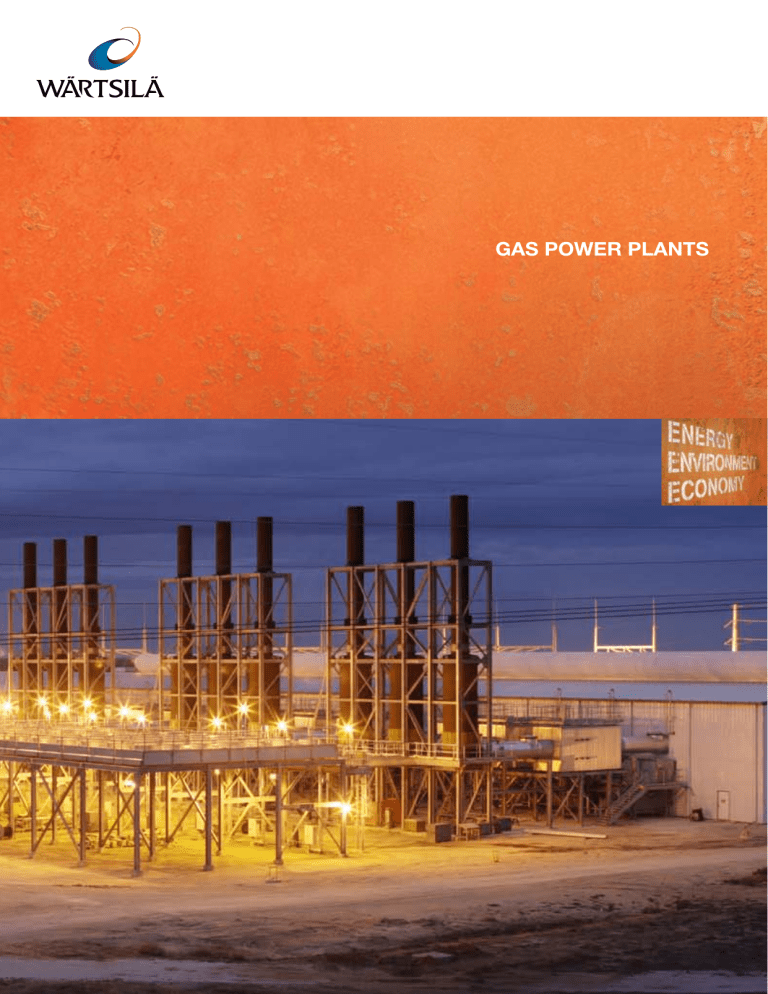
GAS POWER PLANTS The Sheki power plant in Azerbaijan is equipped with 10 x Wärtsilä 20V34SG engines. WÄRTSILÄ GAS POWER PLANTS’ BENEFITS: • Net plant electrical efficiency over 52% • Fast start-up – 5 min from hot standby to full plant load • Combined heat and power as an option • Maintenance schedule independent of the number of starts, stops or trips • Full plant output at high altitudes and in hot and dry ambient conditions • Excellent plant availability and reduced need for back-up capacity due to multi-unit installation • Minimal water consumption due to closed-circuit • High part-load efficiency • Stepwise investment with smaller risks and • Low gas pressure requirement 2 radiator cooling optimized profit generation. GAS POWER PLANTS THAT KEEP YOU IN CONTROL. Whether you need baseload, intermediate, peaking or standby power generation, we provide it. WÄRTSILÄ® gas engine plants are typically based on modular 4–19 MW gas engine units. The engines are designed for continuous operation on natural gas or in dualfuel mode (gas/oil). Our gas power plants offer high output and efficiency even in the most challenging conditions and locations. In the hottest deserts or high in the mountains, in city centres or jungles, energy output and efficiency is consistent and reliable, throughout the entire load range. And the fact that a negligible amount of water is consumed in the process has obvious advantages, too, particularly in dry locations. World-class operational flexibility with uniquely fast starts, stops and restarts, ensures perfect control over daily load fluctuations. And as energy demand grows, the high modularity of our products makes it easy to expand your power plant to meet any future changes. You can upgrade your plant at any time without risking operational reliability. After all, several smaller units are, by definition, always more reliable than one large one. Incremental investment also ensures continual competitiveness in today’s volatile market. So, just pay for what you need, when you need it. Finally, our technologies are backed up by world-wide operations and management services that ensure efficiency and optimize equipment reliability throughout its lifecycle. We offer true flexibility, both in fuel choice and in our ability to respond to operational demand, and this makes Wärtsilä gas power plants the solid choice in today’s power market. GAS POWER PLANTS BY WÄRTSILÄ •• More than 700 power plants •• More than 1800 gensets •• Over 10 GW out there! •• In more than 70 countries 3 LIFETIME COMMITMENT Count on our total commitment and comprehensive range of services – tailored to your requirements – to achieve the best possible performance from your power plant investment throughout its lifecycle. 4 Wärtsilä carries out deliveries ranging from equipment supply, or equipment and engineering, to complete turnkey projects that include engineering, procurement and construction. Our development and finance group, together with a comprehensive service network, make for a complete project implementation, from concept and financing to construction and beyond. Our range of services covers everything from rapid spare parts delivery to complete operations and maintenance solutions. By optimizing all aspects of the power plant’s operations and minimizing the economic and technological risks involved, we enhance the plant’s profitability. Our continuously growing number of Operations & Management (O&M) customers stands as proof. Wärtsilä currently operates more than 130 plants around the world, making it the world’s leading power plant O&M contractor. If you choose to operate the plant yourself, you can still rest assured that you have the best possible support available when and where you need it – from training and online support to service packages or plant modernization and upgrading. Our global network of more than 11,200 professionals worldwide stands ready to provide you with the support you need, anywhere at any time.This ensures that your power plant will operate at its highest efficiency and performance levels throughout its lifetime. We have a track record of providing close to 43 GW of power in 165 countries. Here are just a few examples. CEMENTOS DIAMANTE, COLOMBIA ARKAY, INDIA Type of customer:.....................Industry – cement Engine type:........................5 x Wärtsilä 18V34SG Total output:.............................................27 MW Type of fuel:...................................................Gas Load:....................................................Baseload Type of customer:....................................... Utility Engine type:......................10 x Wärtsilä 20V34SG Total output:..........................................87.3 MW Type of fuel:...................................................Gas Load:....................................................Baseload COVE, TRINIDAD AND TOBAGO ALIAGA TURKEY PLAINS END I & II, COLORADO, USA UTE LINHARES, LINHARES-ESPIRITO SANTO, BRAZIL Type of customer:....................................... Utility Engine type:........................ 4 x Wärtsilä 18V50DF Total output:.............................................64 MW Type of fuel:...................................................Gas Load:....................................................Baseload Type of customer:...........................................IPP Engine type:......................20 x Wärtsilä 18V34SG ................................... + 14 x Wärtsilä 20V34SG Total output:.................................. 113+118 MW Type of fuel:...................................................Gas Load:........................... Peaking power generation Type of customer:...........................................IPP Engine type: .....................28 x Wärtsilä 20V34SG Total output:...........................................244 MW Type of fuel:...................................................Gas Load:......................... Baseload power generation Type of customer:...........................................IPP Engine type:......................24 x Wärtsilä 20V34SG Total output:...........................................204 MW Type of fuel:...................................................Gas Load:........................... Peaking power generation BONTANG, INDONESIA BARRICK, NEVADA, USA KHACHMAZ, AZERBAIJAN SANGACHAL, AZERBAIJAN Type of customer:....................................... Utility Engine type:........................2 x Wärtsilä 16V34SG Total output:.............................................14 MW Type of fuel:...................................................Gas Load:....................................................Baseload Type of customer:....................................... Utility Engine type:......................10 x Wärtsilä 20V34SG Total output:.............................................87 MW Type of fuel:...................................................Gas Load:....................................................Baseload Type of customer:......................Industry – mining Engine type:......................14 x Wärtsilä 20V34SG Total output:...........................................116 MW Type of fuel:...................................................Gas Load:....................................................Baseload Type of customer:....................................... Utility Engine type:...................... 18 x Wärtsilä 18V50DF Total output:...........................................308 MW Type of fuel:...................................................Gas Load:....................................................Baseload 5 Selective Catalytic Reduction unit (SCR) Control room Switchgear room The generating set FLEXIBILITY IN SCOPE Wärtsilä gas power plants are designed for optimal performance in a wide variety of decentralized power production applications: baseload, peaking power and combined heat & power plants. The plant can be situated in the midst of a densely populated area or in a remote area with minimal infrastructural resources. Regardless of the plant’s location, it will be just as lean, clean and quiet as it should be. 6 Modularity simplifies plant configuration to meet each customer’s specific needs. Adding features is a matter of adding modules which are pretested for compatibility and reliability. Pre-engineered, integrated solutions speed up the planning and delivery process, quickly creating savings and added revenue. A typical Wärtsilä gas power plant consignment consists of • generating sets • mechanical auxiliary systems including the A Wärtsilä GasCube plant is a multiple of engine modules designed to meet a total power need of 6–30 MW. A GasCube based on the Wärtsilä 16V34SG or Wärtsilä 20V34SG, with all the auxiliaries and components needed to make up a working power production unit, provides 7–9 MWe per unit. Due to the self contained design, the GasCube is the optimal solution for agile, streamlined and exceptionally cost efficient project execution. • High electrical efficiency • Minimization of the plant’s own electricity consumption • Simple and reliable technical solutions • Compact, pre-engineered plant design • Perfect for EPC deliveries even to areas lacking infrastructure. Compact auxiliary module fuel system, lubrication, air intake, cooling, exhaust processing and sound-proofing • electrical systems • automation • heat recovery system in combined heat and power plants • civil works and structures. Installing a steam boiler to drive a steam turbine will increase the power production by close to 10%. The steam cycle option can either be included in the initial design, or added at a later date. In CHP applications for hot water production Closed-loop cooling system with radiators the total efficiency can reach 95%. This lowers the production cost of electricity and increases the economic attraction of these plants. The environmental impact of a Wärtsilä gas plant is low. NOX emission levels fulfill the majority of global emission requirements today without any secondary cleaning methods. To further reduce environmental impact, effective oxidation and/or NOX catalysts and other advanced equipment can be installed. The engine cooling arrangement using closed-circuit radiator cooling reduces plant process water consumption to almost zero, minimizing the effect on local water resources. The hall design and low building profile help the plant to blend in with its surroundings. Effective sound-proofing allows the plant to be operated even in densely populated areas where the actual loads are, which effectively prevents possible transmission and distribution bottlenecks. 7 FLEXIBILITY IN OPERATION A reciprocating engine is today’s most efficient means of converting liquid or gaseous fuels into energy. Wärtsilä gas power plants can run on low-pressure gas. The dual-fuel option gives even more flexibility when the gas supply is unreliable. 8 Wärtsilä gas engines operate on most natural gas types. They are also available as dualfuel engines, operating on natural gas as well as on diesel fuel. When the gas supply is uncertain or prices are volatile, it is possible to switch over from gas to diesel or vice versa during continuous operation if necessary. The option to run on diesel as a backup fuel can considerably improve reliability in case of gas shortages. In emerging gas markets it is possible to build a fast track plant operating on liquid fuel, and later expand and convert the plant to operate on gas as the supply becomes more readily available. This also works the other way around: existing power plants with gas conversion possibilities create a good base for investments in gas infrastructure. Wärtsilä gas engines with modern lean-burn technology reach over 45% electrical efficiency. The heat recovery option does not affect the electrical efficiency of the generating set. High efficiency translates into considerable savings in fuel costs compared to other technologies. Multi-unit configuration creates a part-load profile that enables you to optimize the entire output range of the plant. For a given total plant load, you simply operate as many individual generating sets as required at their optimal efficiency. Wärtsilä gas power plants withstand extreme conditions, with only minimal heat 1.05 Wärtsilä reciprocating gas engines offer stable output and high performance in hot and dry conditions. No water consumed for plant cooling = arid area suitability! Derating due to cooling water temperature. (Derating due to inlet air temperature starts at 45 °C) Derating factor 1 Wärtsilä 20V34SG (radiator cooling) 0.95 Aeroderivate gas turbine 0.9 Industrial gas turbine 0.85 0.8 15 20 25 30 35 40 45 Ambient temperature (°C) 1.1 1.05 1 Derating factor Wärtsilä reciprocating gas engines offer stable output and high performance at high altitudes as well. Wärtsilä 20V34SG (radiator cooling) 0.95 0.9 0.85 Industrial gas turbine 0.8 Aeroderivate gas turbine 0.75 0.7 0.65 0 500 1000 1500 Altitude [m] 2000 2500 3000 120 Start-up and loading of a gas engine power plant compared to a gas turbine combined cycle. Gas engine 100 Load % 80 Gas turbine combined cycle 60 40 20 0 0 40 60 80 100 Minutes 120 140 160 180 45 The multi-unit gas engine power plant has very high part-load efficiency. 40 Electrical efficiency (%) rate and output derating at high altitudes or in hot temperatures. Furthermore, Wärtsilä gas power plants can be located virtually anywhere due to the fact that our plants run on low gas pressure and their air cooled system does not consume any process water. The multiple genset concept ensures high reliability and availability. All maintenance can be performed on-site one unit at a time, leaving the remaining units available for duty. The use of several identical engines also reduces the cost of on-site spare parts stock. 20 35 5 x Wärtsilä 20V34SG 30 Industrial gas turbine 25 20 15 10 5 0 0 5 10 15 20 25 30 35 40 Plant electrical power (MW) 9 FLEXIBILITY IN FUEL LEAN-BURN GAS ENGINES (SG) The SG engines are spark-ignited lean-burn engines. In this process, the gas is mixed with air before the inlet valves. During the intake period, gas is also fed into a small prechamber, where the gas mixture is rich compared to the gas in the cylinder. At the end of the compression phase the gas-air mixture in the prechamber is ignited by a spark plug. The flames from the nozzle of the prechamber ignite the gas-air mixture in the whole cylinder. Combustion is fast. After the working phase the cylinder is emptied of exhaust and the process starts again. The engine generating sets used in Wärtsilä power plants are driven by heavy-duty medium-speed four-stroke reciprocating engines. These generating sets consist of an engine connected directly to a generator via a flexible coupling. The generator and engine are rigidly mounted on a common baseframe. SG PRINCIPLE DUAL-FUEL ENGINES (DF) The dual-fuel engine utilizes a “lean-burn” combustion process when operating on gas. Here, the gas is mixed with air before the intake valves during the air intake period. After the compression phase, the gas-air mixture is ignited by a small amount of liquid pilot fuel. After the working phase the exhaust gas valves open and the cylinder is emptied of exhaust gases. The inlet air valves open when the exhaust gas valves close, and the process starts again. The dual-fuel engine is also equipped with a back-up fuel system. This is a normal diesel process with camshaft-operated liquid fuel pumps running parallel to the process and working as a stand-by. DF PRINCIPLE Liquid fuel Gas fuel Gas Gas Inlet Compression Combustion Outlet Inlet Compression Combustion Outlet GAS POWER PLANT OUTPUT RANGE Gas engines Wärtsilä 34SG Wärtsilä 50SG Dual-fuel engines (gaseous fuel/liquid fuel) Wärtsilä 32GD Wärtsilä 34DF Wärtsilä 50DF 10 MW 1 5 10 50 100 300 500 GAS ENGINES Wärtsilä 34SG GAS-DIESEL ENGINES (GD) The GD engine utilizes the diesel combustion process in all operational modes. In gas mode, the gas is injected at high pressure after the pilot fuel and is ignited by the flame from the pilot fuel injection. The amount of pilot fuel is equivalent to approximately 5% of the fuel energy input at full engine load. The gas-diesel engine can be switched over instantly to liquid fuel mode operation. The liquid fuel can be light fuel oil, heavy fuel oil or crude oil. In this case, the process is the same as the conventional diesel process. In fuel sharing mode, the ratio between liquid and gas fuel amounts can be controlled and varied during operation. The operating window for the fuel sharing mode is 30 to 100% load and the gas/liquid fuel ratio can vary according to the fuel sharing window. The gas-diesel process can tolerate big variations in the gas quality and is especially suitable for “non-pipeline quality gas”, such as associated gas in oil fields. Technical data 50 Hz/750 rpm Unit Power, electrical kW Heat rate kJ/kWh Electrical efficiency % Technical data 60 Hz/720 rpm Power, electrical kW Heat rate kJ/kWh Electrical efficiency % Dimensions and dry weight of generating set Length mm Width mm Height mm Weight tonne 9L34SG 4343 7843 45.9 16V34SG 7744 7819 46.0 20V34SG 9730 7779 46.3 4169 7843 45.9 7434 7819 46.0 9341 7779 46.3 10400 2780 3840 77 11300 3300 4240 120 12890 3300 4440 130 Heat rate and electrical efficiency at generator terminals, including engine driven pumps, ISO 3046 conditions and gas LHV > 28 MJ/m3N. Tolerance 5%. Power factor 0.8. Gas Methane Number > 80. Nm3 defined at NTP (273.15 K and 101.3 kPa). Wärtsilä 50SG Technical data 50 Hz/500 rpm Unit Power, electrical kW Heat rate kJ/kWh Electrical efficiency % Technical data 60 Hz/514 rpm Power, electrical kW Heat rate kJ/kWh Electrical efficiency % Dimensions and dry weight of generating set Length mm Width mm Height mm Weight tonne 18V50SG 18 320 7411 48.6 18 759 7411 48.6 18 800 5330 6340 360 Heat rate and electrical efficiency at generator terminals, including engine driven pumps, ISO 3046 conditions and gas LHV > 28 MJ/m3N. Tolerance 5%. Power factor 0.8. Gas Methane Number > 80. Nm3 defined at NTP (273.15 K and 101.3 kPa). GD PRINCIPLE DUAL-FUEL ENGINES Wärtsilä 34DF Gas fuel Liquid fuel Technical data 50 Hz/750 rpm 6L34DF Power, electrical kW 2579 Heat rate kJ/kWh 8347 (8257)* Electrical efficiency % 43.1 (43.6)* Technical data 60 Hz/720rpm Power, electrical kW 2493 Heat rate kJ/kWh 8347 (8437)* Electrical efficiency % 43.1 (42.7)* Dimensions and dry weight of generating set Length mm 8400 Width mm 2780 Height mm 3840 Weight tonne 58 9L34DF 16V34DF 20V34DF 3888 6970 8730 8303 (8214)* 8048 (8146)* 8031 (8127)* 43.4 (43.8)* 44.7 (44.1)* 44.8 (44.3)* 3758 6737 8439 8303 (8175)* 8048 (8107)* 8031 (8127)* 43.4 (44.0)* 44.7 (44.4)* 44.8 (44.3)* 10400 2780 3842 77 11300 3300 4240 120 12890 3300 4440 130 Heat rate and electrical efficiency at generator terminals, including engine driven pumps, ISO 3046 conditions and gas LHV > 28 MJ/Nm3. Tolerance 5%. Power factor 0.8. Gas Methane Number > 80. Nm3 defined at NTP (273.15 K and 101.3 kPa). *In liquid fuel mode. Inlet Compression Combustion Outlet Wärtsilä 50DF Technical data 50 Hz/500 rpm Unit Power, electrical kW Heat rate kJ/kWh Electrical efficiency % Technical data 60 Hz/514 rpm Power, electrical kW Heat rate kJ/kWh Electrical efficiency % Dimensions and dry weight with generating set Length mm Width mm Height mm Weight tonne 18V50DF 16638 7498 48.0 18V50DF* 16638 7933 45.4 17076 7489 48.0 17076 7933 45.4 18780 4090 6020 355 18780 4090 6020 355 Heat rate and electrical efficiency at generator terminals, including engine driven pumps, ISO 3046 conditions and gas LHV > 28 MJ/Nm3. Tolerance 5%. Power factor 0.8. Gas Methane Number > 80. Nm3 defined at NTP (273.15 K and 101.3 kPa). *In liquid fuel mode. Wärtsilä 32GD Technical data 50 Hz/750 rpm 6L32GD Power, electrical kW 2636 Heat rate kJ/kWh 8304 Electrical efficiency % 43.4 Technical data 60 Hz/720rpm Power, electrical kW 2579 Heat rate kJ/kWh 8304 Electrical efficiency % 43.4 Dimensions and dry weight of generating set Length mm 8400 Width mm 2780 Height mm 3840 Weight tonne 58 9L32GD 3974 8260 43.6 12V32GD 16V32GD 20V32GD 5299 7124 8924 8091 8066 8049 44.5 44.6 44.7 3888 8260 43.6 5184 8091 44.5 6970 8066 44.6 8730 8049 44.7 10400 2780 3840 77 10200 3300 4470 92 11300 3300 4240 120 12890 3300 4440 130 Heat rate and electrical efficiency at generator terminals, including engine driven pumps, ISO 3046 conditions and gas LHV > 36 MJ/m3N. Lower LHV can be compensated by liquid fuel. Tolerance 5%. Power factor 0.8. Gas pressure at engine inlet 350 bar. Nm3 defined at NTP (273.15 K and 101.3 kPa). 11 Wärtsilä is a global leader in complete lifecycle power solutions for the marine and energy markets. By emphasising technological innovation performance of the vessels and power plants of its customers. Wärtsilä is listed on the NASDAQ OMX Helsinki, Finland. WÄRTSILÄ® is a registered trademark. Copyright © 2011 Wärtsilä Corporation. DBAB540960 – 08.2011 / Bock´s Office / Waasa Graphics and total efficiency, Wärtsilä maximises the environmental and economic
